Topic i squared c: The I Squared C (I2C) protocol is a fundamental technology in electronics, enabling efficient communication between integrated circuits. This comprehensive guide explores the basics, features, and applications of I2C, providing valuable insights for both beginners and experienced engineers. Discover how I2C simplifies complex communication systems in today's advanced digital devices.
Table of Content
- I²C (Inter-Integrated Circuit)
- Introduction to I2C
- History and Development of I2C
- How I2C Works
- Key Features of I2C
- Common Applications of I2C
- I2C Bus Specifications
- I2C Protocol Basics
- Addressing in I2C
- Data Transfer in I2C
- I2C Bus Speed Modes
- Multi-Master Configuration
- Slave Devices in I2C
- I2C Signals and Levels
- Clock Synchronization
- Arbitration Process
- Acknowledgment Mechanism
- Clock Stretching
- Repeated Start Condition
- YOUTUBE: Khám phá I2C, một giao thức giao tiếp quan trọng trong các hệ thống nhúng. Video này cung cấp cái nhìn tổng quan về cách I2C hoạt động và ứng dụng của nó.
I²C (Inter-Integrated Circuit)
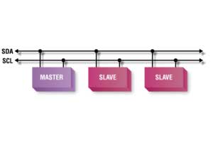
I²C, also known as I-squared-C, stands for Inter-Integrated Circuit. It is a multi-master, multi-slave, packet-switched, single-ended, serial computer bus invented by Philips Semiconductor (now NXP Semiconductors). It is widely used for attaching lower-speed peripheral ICs to processors and microcontrollers in short-distance, intra-board communication.
Key Features of I²C
- Simple 2-wire communication protocol
- Uses serial data (SDA) and serial clock (SCL) lines
- Supports multiple masters and slaves on the same bus
- Operates in different speed modes: Standard (100 kbps), Fast (400 kbps), Fast Mode Plus (1 Mbps), High-Speed (3.4 Mbps), and Ultra-Fast (5 Mbps)
- 7-bit or 10-bit addressing scheme
How I²C Works
In I²C communication, devices are classified as either masters or slaves. The master generates the clock signal and initiates communication with slaves. The process involves the following steps:
- The master sends a start condition by pulling SDA low while SCL is high.
- The master sends the 7-bit or 10-bit address of the target slave device along with a read/write bit.
- The addressed slave device responds with an acknowledgment (ACK) bit.
- Data transfer occurs between the master and the slave.
- The master sends a stop condition by releasing SDA while SCL is high.
Data Transfer Rates
| Mode | Data Transfer Speed | Direction |
|---|---|---|
| Standard | 100 Kbits/sec | Bi-directional |
| Fast | 400 Kbits/sec | Bi-directional |
| Fast Mode Plus (Fm+) | 1 Mbits/sec | Bi-directional |
| High-Speed (Hs) | 3.4 Mbits/sec | Bi-directional |
| Ultra-Fast (UFm) | 5 Mbits/sec | Uni-directional |
Advantages of I²C
- Reduces the number of I/O pins on microcontrollers
- Supports multiple devices on a single bus
- Low power consumption
- Simple hardware configuration
- Robust communication with built-in error detection and correction
Applications of I²C
- Sensors
- Memory devices
- Real-time clocks
- Display controllers
- Data converters
Arbitration and Clock Stretching
In I²C, multiple masters can be connected to the same bus. Arbitration ensures that if two masters initiate communication simultaneously, one of them will control the bus without message corruption. Clock stretching allows slaves to hold the clock line low to signal the master to wait, enabling slower devices to communicate effectively.
Comparison with Other Communication Protocols
- SPI: Faster data rates and full-duplex communication but requires more pins and does not support multiple masters.
- UART: Simpler, point-to-point communication without a dedicated clock line, but typically not suitable for multi-device communication on the same bus.
- USB: Higher data rates and more complex protocol, typically used for longer-distance communication between devices.

READ MORE:
Introduction to I2C
The Inter-Integrated Circuit (I2C) protocol, also known as I Squared C, is a multi-master, multi-slave, packet-switched, single-ended, serial communication bus widely used in electronics. Developed by Philips Semiconductor in 1982, I2C enables communication between microcontrollers and peripheral devices such as sensors, displays, and memory modules with minimal pin usage.
I2C operates using two lines:
- SDA (Serial Data Line)
- SCL (Serial Clock Line)
The protocol is designed to facilitate the transfer of data between components on the same circuit board, allowing devices to communicate using a simple and efficient method. Here are the key features of I2C:
- Supports multiple masters and slaves on the same bus.
- Uses two bi-directional open-drain lines, pulled up with resistors.
- Employs addressing to identify devices uniquely.
- Includes built-in support for collision detection and arbitration to manage multiple masters.
Communication in I2C involves a master device initiating a data transfer and a slave device responding. The master generates the clock signal and controls the flow of data, while the slave follows the master's instructions. The basic steps in an I2C communication are:
- Start Condition: The master pulls the SDA line low while the SCL line is high.
- Address Frame: The master sends a 7-bit address followed by a read/write bit to select the slave device.
- Acknowledgment (ACK/NACK): The addressed slave responds with an acknowledgment signal.
- Data Transfer: Data is transmitted in 8-bit bytes, with the master and slave alternating in sending and acknowledging each byte.
- Stop Condition: The master releases the SDA line while the SCL line is high, ending the communication.
I2C's simplicity and efficiency make it ideal for short-distance communication within a single device or between components on a PCB, making it a fundamental technology in modern electronics.
History and Development of I2C
The Inter-Integrated Circuit (I2C) protocol, created by Philips Semiconductor (now NXP Semiconductors) in 1982, was developed to simplify the communication between integrated circuits in consumer electronics. The goal was to reduce the complexity and the number of connections needed on a printed circuit board (PCB).
The evolution of I2C can be summarized as follows:
- 1982: Philips introduces the I2C protocol to connect microcontrollers with peripheral devices in televisions, aiming for efficient and straightforward communication.
- 1992: The first major update to the protocol introduces a faster mode, increasing the standard speed from 100 kbit/s to 400 kbit/s, known as Fast-mode (Fm).
- 1998: Fast-mode Plus (Fm+) is released, pushing the speed further to 1 Mbit/s, enabling quicker data transfers and accommodating more demanding applications.
- 2000: The High-speed mode (Hs-mode) is developed, allowing speeds up to 3.4 Mbit/s, suitable for advanced applications that require rapid data communication.
- 2012: The Ultra Fast-mode (UFm) is introduced, achieving speeds of up to 5 Mbit/s, making I2C a versatile protocol for a wide range of applications.
The design of I2C focuses on simplicity and efficiency. It uses only two bidirectional lines, SDA (Serial Data Line) and SCL (Serial Clock Line), to transmit information between devices. This minimalistic design has contributed significantly to its adoption across various industries, including automotive, medical, and telecommunications.
Throughout its history, I2C has maintained backward compatibility, ensuring that newer devices can communicate with older ones, preserving investments in existing technologies. Its robust design, combined with ongoing enhancements, continues to make I2C an integral part of modern electronics.
The protocol's widespread adoption and continuous development reflect its importance in the electronics industry. From its inception to the present day, I2C has evolved to meet the growing demands for faster, more reliable communication between integrated circuits.
How I2C Works
The Inter-Integrated Circuit (I2C) protocol facilitates communication between multiple integrated circuits using just two wires: SDA (Serial Data Line) and SCL (Serial Clock Line). Here’s a detailed step-by-step explanation of how I2C works:
- Start Condition: Communication begins with a start condition, where the master device pulls the SDA line low while the SCL line is high.
- Addressing: The master sends a 7-bit address of the target slave device, followed by a read/write bit (0 for write, 1 for read).
- Acknowledgment (ACK/NACK): The addressed slave responds with an acknowledgment by pulling the SDA line low. If no slave responds, the master can issue a stop condition or retry the communication.
- Data Transfer: Data is transferred in 8-bit bytes. Each byte sent by the master or slave is followed by an acknowledgment bit from the receiver. The steps involved in data transfer are:
- The sender releases the SDA line and sets the next data bit.
- The receiver reads the data bit when the SCL line is high.
- After 8 bits are transferred, the receiver sends an acknowledgment by pulling the SDA line low.
- Repeated Start Condition: The master can issue a repeated start condition if it needs to communicate with another device or change the transfer direction without releasing the bus.
- Stop Condition: The master ends the communication by releasing the SDA line while the SCL line is high.
Here’s an overview of I2C communication:
| Step | Description |
|---|---|
| Start Condition | Master pulls SDA low, then SCL low. |
| Address Frame | Master sends 7-bit address + read/write bit. |
| Acknowledgment | Slave responds with ACK by pulling SDA low. |
| Data Transfer | Data sent in 8-bit frames, followed by ACK/NACK. |
| Repeated Start | Optional start condition for continuous communication. |
| Stop Condition | Master releases SDA while SCL is high. |
I2C’s design allows multiple devices to share the same bus, with each device having a unique address. This makes I2C an efficient and flexible protocol for communication between integrated circuits in various applications.
Key Features of I2C
The Inter-Integrated Circuit (I2C) protocol offers several key features that make it a popular choice for communication between integrated circuits. These features contribute to its flexibility, efficiency, and ease of use in a wide range of applications:
- Simple Two-Wire Interface: I2C uses only two bidirectional lines, SDA (Serial Data Line) and SCL (Serial Clock Line), which simplifies circuit design and reduces the number of pins needed on microcontrollers and peripherals.
- Multi-Master and Multi-Slave Capability: I2C supports multiple master and slave devices on the same bus, allowing for versatile and complex communication networks within a single system.
- Addressing: Each device on the I2C bus has a unique 7-bit or 10-bit address, enabling precise communication between the master and a specific slave device. The 7-bit address space allows for up to 128 unique device addresses.
- Speed Modes: I2C supports various speed modes to cater to different performance requirements:
- Standard Mode: Up to 100 kbit/s
- Fast Mode: Up to 400 kbit/s
- Fast Mode Plus: Up to 1 Mbit/s
- High-Speed Mode: Up to 3.4 Mbit/s
- Ultra Fast Mode: Up to 5 Mbit/s
- Clock Synchronization and Arbitration: I2C includes mechanisms for clock synchronization and arbitration, ensuring reliable communication even when multiple masters are active on the bus. This feature helps to prevent data collisions and ensures orderly data transmission.
- Acknowledgment Mechanism: After each byte of data is transmitted, the receiver sends an acknowledgment (ACK) or a negative acknowledgment (NACK) signal. This feedback allows the sender to verify successful data transfer and take appropriate actions if errors occur.
- Clock Stretching: Slaves can hold the clock line low to delay the master's clock signal if they need more time to process data, allowing for better synchronization and flexibility in data handling.
- Low Power Consumption: I2C's design minimizes power consumption, making it suitable for battery-powered and energy-efficient devices.
- Scalability: I2C's ability to support multiple devices and its compatibility with various speed modes make it scalable for use in small, simple systems as well as larger, more complex networks.
These key features make I2C a versatile and efficient protocol for communication between integrated circuits, widely used in various applications such as sensors, displays, memory modules, and more.
Common Applications of I2C
The Inter-Integrated Circuit (I2C) protocol is widely used in various applications due to its simplicity, efficiency, and versatility. Here are some of the common applications of I2C:
- Sensors: I2C is often used to interface with various sensors, such as temperature, humidity, pressure, and accelerometers. These sensors communicate their data to microcontrollers or processors in applications like weather stations, industrial monitoring, and wearable devices.
- Displays: I2C is employed to control character and graphical LCDs, OLEDs, and other display modules in consumer electronics, instrumentation, and control panels. It allows easy management of display data with minimal wiring.
- EEPROM and Memory Devices: I2C is commonly used to interface with EEPROMs (Electrically Erasable Programmable Read-Only Memory) and other memory devices. These memory modules store configuration data, calibration parameters, and other essential information in embedded systems.
- Real-Time Clocks (RTC): Real-time clock modules use I2C to provide accurate timekeeping in devices such as computers, embedded systems, and IoT devices. The I2C interface simplifies the integration of RTCs into various applications.
- Communication Modules: I2C is utilized in communication modules like GSM, GPS, and Bluetooth to manage configuration and data transfer between the microcontroller and the communication module, facilitating connectivity in various applications.
- Digital-to-Analog Converters (DAC) and Analog-to-Digital Converters (ADC): I2C interfaces with DAC and ADC modules to convert digital signals to analog and vice versa, enabling precise data acquisition and control in measurement and instrumentation systems.
- Keypads and Input Devices: I2C is used to connect keypads, touchscreens, and other input devices to microcontrollers, simplifying the detection and processing of user inputs in consumer electronics, automotive interfaces, and industrial control panels.
- Power Management ICs: I2C enables communication with power management integrated circuits (PMICs) to control and monitor power distribution, voltage regulation, and battery management in portable devices, laptops, and embedded systems.
- Audio Codecs: I2C interfaces with audio codecs to manage audio data transfer, volume control, and sound processing in multimedia devices, smartphones, and audio equipment.
- Microcontroller Communication: I2C facilitates communication between multiple microcontrollers in a system, allowing them to share data, coordinate actions, and perform distributed processing tasks efficiently.
These applications highlight the flexibility and utility of I2C in various domains, making it an essential protocol in modern electronics design and development.
I2C Bus Specifications
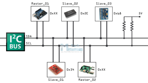
The Inter-Integrated Circuit (I2C) bus is a widely used communication protocol with well-defined specifications that ensure reliable and efficient data transfer between devices. Here are the key specifications of the I2C bus:
- Bus Configuration:
- Two-Wire Interface: The I2C bus uses two bidirectional lines: SDA (Serial Data Line) and SCL (Serial Clock Line).
- Pull-Up Resistors: Both lines are connected to a positive supply voltage via pull-up resistors, ensuring the lines are high when idle.
- Addressing:
- 7-Bit Addressing: Standard I2C devices use a 7-bit address, allowing for 128 unique addresses.
- 10-Bit Addressing: An extended mode supports 10-bit addressing, increasing the address space to 1024 unique addresses.
- Data Transfer Rates:
- Standard Mode: Up to 100 kbit/s.
- Fast Mode: Up to 400 kbit/s.
- Fast Mode Plus: Up to 1 Mbit/s.
- High-Speed Mode: Up to 3.4 Mbit/s.
- Ultra Fast Mode: Up to 5 Mbit/s.
- Data Transfer Format:
- Start Condition: Initiated by the master by pulling SDA low while SCL is high.
- Stop Condition: Initiated by the master by releasing SDA while SCL is high.
- Data Frame: Consists of 8 bits, followed by an acknowledgment (ACK) or non-acknowledgment (NACK) bit.
- Repeated Start Condition: Allows the master to initiate a new transfer without releasing the bus.
- Clock Synchronization:
- Clock Stretching: Slaves can hold the clock line low to delay the master's clock signal, allowing more time for data processing.
- Arbitration:
- Multi-Master Support: Multiple masters can exist on the same bus. Arbitration ensures that only one master controls the bus at any time.
The I2C bus specifications are designed to provide robust and flexible communication between integrated circuits, making it suitable for a wide range of applications in consumer electronics, automotive, industrial, and medical devices.
I2C Protocol Basics
The Inter-Integrated Circuit (I2C) protocol is a simple, yet powerful, communication protocol used to connect multiple devices using just two wires. Here are the basics of how the I2C protocol works:
- Bus Structure:
- SDA (Serial Data Line): Used for data transfer between devices.
- SCL (Serial Clock Line): Carries the clock signal generated by the master device to synchronize data transfer.
- Roles:
- Master: The device that initiates communication and generates the clock signal.
- Slave: The device that responds to the master's commands and does not generate the clock signal.
- Addressing:
- Each slave device has a unique 7-bit or 10-bit address.
- The master uses this address to communicate with a specific slave device.
- Data Transfer:
- Start Condition: The master initiates communication by pulling SDA low while SCL is high.
- Address Frame: The master sends the 7-bit address of the slave and a read/write bit (0 for write, 1 for read).
- Acknowledgment (ACK/NACK): The slave responds with an ACK by pulling SDA low or a NACK by leaving SDA high.
- Data Frame: Data is transferred in 8-bit bytes, with each byte followed by an ACK or NACK bit from the receiver.
- Repeated Start Condition: The master can issue a repeated start condition without releasing the bus to initiate another communication sequence.
- Stop Condition: The master ends communication by releasing SDA while SCL is high.
- Clock Synchronization:
- Clock Stretching: Slaves can hold the SCL line low to delay the clock signal if they need more time to process data.
- Arbitration:
- When multiple masters are present, arbitration ensures that only one master controls the bus at a time by monitoring the SDA line and backing off if another master is transmitting.
The I2C protocol's simplicity and flexibility make it ideal for a wide range of applications, including communication with sensors, displays, memory devices, and more. Its efficient two-wire design minimizes the number of pins needed and supports multiple devices on the same bus, making it a fundamental tool in modern electronics.
Addressing in I2C
The I2C (Inter-Integrated Circuit) protocol employs addressing to facilitate communication between multiple devices on the same bus. Each device connected to the I2C bus is assigned a unique address which the master device uses to communicate with specific slave devices.
7-bit and 10-bit Addressing
I2C supports two types of addressing schemes: 7-bit and 10-bit addressing. The 7-bit addressing scheme is more common and supports up to 128 unique addresses. The 10-bit addressing scheme expands this capability, allowing for 1024 unique addresses.
- 7-bit Addressing: In 7-bit addressing, the address is sent in the first byte after the start condition. The most significant bit (MSB) is typically the read/write bit.
- 10-bit Addressing: For 10-bit addressing, the first two bytes are used. The first byte starts with a special 5-bit pattern (11110) followed by the two most significant bits of the address. The second byte contains the remaining 8 bits of the address.
Address Format
The I2C address format consists of the following parts:
- Address bits: These are the bits that define the unique address of the device.
- R/W bit: The least significant bit (LSB) indicates whether the master is reading from (1) or writing to (0) the slave device.
For example, in a 7-bit address format, the address might look like this:
| A6 | A5 | A4 | A3 | A2 | A1 | A0 | R/W |
Reserved Addresses
Some addresses are reserved for specific purposes and cannot be assigned to devices. For instance:
- 0000 000: General call address
- 1111 111: Reserved for future use
Device Addressing Process
The addressing process in I2C involves the following steps:
- The master device initiates communication by sending a start condition.
- The master then sends the address of the target slave device along with the R/W bit.
- If the address matches a slave device, the slave acknowledges the master's request by pulling the data line (SDA) low.
Address Conflicts and Solutions
Address conflicts can occur if two devices share the same address. To resolve this:
- Ensure all devices have unique addresses.
- Use address pins if the device supports them to configure different addresses.
- Implement a software-based addressing scheme if necessary.
Example of Addressing in I2C Communication
Consider a scenario where a master device communicates with a slave device at address 0x50:
| 0 | 1 | 0 | 1 | 0 | 0 | 0 | 0 | R/W |
The master sends 0x50 followed by the R/W bit to either read from or write to the slave device.

Data Transfer in I2C
Data transfer in I2C (Inter-Integrated Circuit) involves the transmission of data between a master and one or more slave devices on the same bus. The process follows a structured protocol to ensure data integrity and proper communication. Here's a detailed step-by-step explanation:
1. Start Condition
The data transfer begins with the master device sending a start condition. This is achieved by pulling the SDA (Serial Data) line low while the SCL (Serial Clock) line is high.
2. Addressing
Following the start condition, the master sends the address of the target slave device. This address is typically 7 or 10 bits long. The address byte also includes a read/write bit, indicating the operation type:
- 0: Write operation
- 1: Read operation
3. Acknowledgment
After the address is sent, the addressed slave device responds with an acknowledgment (ACK) bit by pulling the SDA line low during the next clock pulse. If no device acknowledges, the master can send a stop condition or retry the addressing.
4. Data Transfer
Data is transferred in bytes (8 bits) with each bit synchronized to the clock signal. The master generates the clock pulses, and data on the SDA line must remain stable during the high period of the clock (SCL). Data transitions are only allowed when SCL is low:
- Each byte of data is followed by an ACK bit from the receiver.
- If the receiver is unable to process more data, it sends a NACK (not acknowledge) by leaving the SDA line high.
5. Repeated Start Condition
For combined read/write operations, a repeated start condition can be sent by the master. This involves generating another start condition without sending a stop condition first, allowing the master to change the communication direction or address a different slave device.
6. Stop Condition
The data transfer is completed by the master sending a stop condition, which is done by releasing the SDA line to high while SCL is high. This signals the end of the communication to all devices on the bus.
Example: Writing Data
When writing data to a slave, the sequence is:
- Master sends a start condition.
- Master sends the slave address with the write bit (0).
- Slave acknowledges the address.
- Master sends the data bytes, each followed by an acknowledgment from the slave.
- Master sends a stop condition to terminate the transfer.
Example: Reading Data
When reading data from a slave, the sequence is:
- Master sends a start condition.
- Master sends the slave address with the read bit (1).
- Slave acknowledges the address.
- Slave sends the data bytes, each followed by an acknowledgment from the master.
- Master sends a NACK after the last byte and then a stop condition.
Conclusion
Understanding the data transfer process in I2C is essential for designing and debugging communication between devices on the I2C bus. Proper implementation ensures reliable data exchange and system performance.
I2C Bus Speed Modes
The I2C (Inter-Integrated Circuit) bus supports multiple speed modes to accommodate different data rate requirements. These modes define the maximum speed at which data can be transferred between devices on the I2C bus. Here are the primary speed modes used in I2C communication:
- Standard Mode (Sm): This is the original speed mode for I2C, supporting data transfer rates up to 100 kbit/s. It is widely used for basic communication between devices.
- Fast Mode (Fm): This mode allows for higher data transfer rates up to 400 kbit/s. It is backward compatible with Standard Mode devices, allowing mixed-speed devices on the same bus.
- Fast Mode Plus (Fm+): This mode increases the maximum data rate to 1 Mbit/s. It also allows for higher bus capacitance, making it suitable for longer distances or more devices.
- High-Speed Mode (Hs): High-Speed Mode supports data rates up to 3.4 Mbit/s. This mode is typically used for applications requiring rapid data transfer, such as video processing or high-speed sensors. Note that additional pull-up resistors and different timing requirements are necessary for this mode.
- Ultra-Fast Mode (UFm): The latest and fastest mode, Ultra-Fast Mode, supports data transfer rates up to 5 Mbit/s. Unlike other modes, it uses a push-pull driver configuration and is unidirectional, which simplifies design but limits the communication to a single direction at a time.
The following table summarizes the key characteristics of each I2C speed mode:
| Mode | Maximum Speed | Maximum Capacitance | Driver Type | Direction |
|---|---|---|---|---|
| Standard Mode (Sm) | 100 kbit/s | 400 pF | Open Drain | Bidirectional |
| Fast Mode (Fm) | 400 kbit/s | 400 pF | Open Drain | Bidirectional |
| Fast Mode Plus (Fm+) | 1 Mbit/s | 550 pF | Open Drain | Bidirectional |
| High-Speed Mode (Hs) | 3.4 Mbit/s | 100 pF | Open Drain | Bidirectional |
| Ultra-Fast Mode (UFm) | 5 Mbit/s | Unknown | Push-Pull | Unidirectional |
Each speed mode in I2C communication offers different benefits and trade-offs, making it suitable for various applications. Selecting the appropriate speed mode depends on factors like data rate requirements, bus length, number of devices, and the specific needs of the application.
Multi-Master Configuration
In a multi-master configuration, the I2C bus allows multiple master devices to control the bus and communicate with slave devices. This setup enhances flexibility and robustness in communication systems but also introduces complexity in bus management. Here is a detailed look at the multi-master configuration in I2C:
-
Arbitration:
When multiple masters attempt to control the bus simultaneously, an arbitration process ensures that only one master takes control. Each master monitors the bus and compares the data it sends with the data on the bus. If a master detects a discrepancy, it stops transmitting, allowing the winning master to continue. Arbitration is based on the clock and data lines. -
Synchronization:
Clock synchronization is crucial in a multi-master system. All masters must synchronize their clocks to avoid conflicts. The bus clock is controlled by the master that drives it low, ensuring all masters operate at the same speed. -
Bus Control:
Control of the bus can be taken by any master during an idle state. The master asserts a start condition and sends the address of the target slave device. If the bus is busy, other masters must wait until the bus is free. -
Clock Stretching:
Slave devices can hold the clock line low to delay the master's communication. This mechanism, known as clock stretching, ensures slaves have enough time to process data, particularly in high-speed transfers. -
Implementation Steps:
- Initialize the I2C bus and configure each master device with a unique address.
- Set up the arbitration and synchronization mechanisms in each master device.
- Implement bus control protocols to manage the start and stop conditions appropriately.
- Ensure all devices support clock stretching to handle communication delays.
- Test the system thoroughly to handle collisions and ensure reliable data transfer.
The multi-master configuration in I2C is powerful but requires careful management of arbitration, synchronization, and bus control to ensure smooth and efficient communication.
Slave Devices in I2C
In an I2C (Inter-Integrated Circuit) bus, communication occurs between a master device and one or more slave devices. Slave devices are essential components that respond to commands issued by the master. They can be sensors, memory chips, display drivers, or other peripherals. Understanding how slave devices operate within the I2C protocol is crucial for designing and troubleshooting I2C systems.
Characteristics of I2C Slave Devices
- Addressable: Each slave device has a unique 7-bit or 10-bit address, allowing the master to identify and communicate with individual slaves on the bus.
- Respond to Master: Slave devices only respond to commands from the master. They do not initiate communication on the I2C bus.
- Data Transmission: Slaves can send or receive data when requested by the master. This data exchange can be read or write operations initiated by the master.
Addressing in I2C
The I2C protocol uses a unique address for each slave device, enabling the master to communicate with specific slaves. The address can be 7-bit or 10-bit, but 7-bit addressing is more common. The master device sends the address along with a read/write bit to indicate the intended operation.
Steps in Communication with a Slave Device
- Start Condition: The master generates a start condition, signaling the beginning of a communication session.
- Address Frame: The master sends the slave address along with the read/write bit. The slave with the matching address responds.
- Acknowledgment: The addressed slave device sends an acknowledgment (ACK) signal back to the master, confirming receipt of the address.
- Data Frame: Depending on the read/write bit, data is either transmitted from the master to the slave (write operation) or from the slave to the master (read operation).
- Stop Condition: The master generates a stop condition, ending the communication session.
Common Slave Devices in I2C Systems
- Sensors: Temperature sensors, accelerometers, gyroscopes, and other sensors often use the I2C protocol to communicate measurements to the master.
- Memory Devices: EEPROM and other memory devices are frequently accessed over I2C for data storage and retrieval.
- Display Controllers: OLED and LCD display controllers commonly use I2C to receive commands and display data from the master.
- Real-Time Clocks: RTC modules use I2C to provide timekeeping functions to the master device.
Implementation Considerations
When designing an I2C system with multiple slave devices, it's important to consider the following:
- Address Conflicts: Ensure that each slave device on the bus has a unique address to avoid conflicts.
- Bus Capacitance: The total capacitance of the I2C bus, including all connected slave devices, should be within the specified limits to ensure reliable communication.
- Pull-Up Resistors: Proper pull-up resistors are required on the SDA (data) and SCL (clock) lines to maintain the integrity of the signals.
Example of I2C Communication with a Slave Device
Consider an example where the master reads temperature data from a sensor slave device:
- The master generates a start condition.
- The master sends the sensor's address along with the read bit.
- The sensor acknowledges the address and read request.
- The sensor sends the temperature data to the master.
- The master receives the data and generates a stop condition to end the communication.
Understanding the role and operation of slave devices in I2C communication is fundamental for successful implementation and troubleshooting of I2C systems. With proper addressing, acknowledgment mechanisms, and careful consideration of bus characteristics, slave devices can effectively communicate with the master, enabling a wide range of applications in embedded systems and other technologies.
I2C Signals and Levels
The I2C protocol operates using two primary signals: the Serial Data Line (SDA) and the Serial Clock Line (SCL). Both lines are open-drain, meaning they are pulled up to a positive supply voltage through pull-up resistors and can be pulled low by devices on the bus.
Signal Description
- SDA (Serial Data Line): This line is used for the bi-directional transmission of data between devices on the I2C bus. Data on the SDA line can be read or written by both the master and the slave devices.
- SCL (Serial Clock Line): This line carries the clock signal generated by the master device. It synchronizes the data transmission on the SDA line. Each bit of data on the SDA line is synchronized with a clock pulse on the SCL line.
Logic Levels
The logic levels for the I2C bus are defined by the voltage levels of the SDA and SCL lines:
- Logic High: When the voltage on the SDA or SCL line is close to the supply voltage (VCC), it represents a logic high (1).
- Logic Low: When the voltage on the SDA or SCL line is close to ground (GND), it represents a logic low (0).
Signal Timing
The I2C protocol defines specific timing requirements for signals to ensure reliable data transmission:
- Start Condition: A start condition is initiated by the master device and occurs when the SDA line transitions from high to low while the SCL line is high.
- Stop Condition: A stop condition is initiated by the master device and occurs when the SDA line transitions from low to high while the SCL line is high.
- Data Validity: Data on the SDA line is considered valid when the SCL line is high. Changes in the SDA line should occur while the SCL line is low.
Electrical Characteristics
The electrical characteristics of the I2C bus are defined to ensure proper communication between devices:
| Parameter | Standard Mode | Fast Mode | High-Speed Mode |
|---|---|---|---|
| Pull-up Resistor Value | 4.7 kΩ | 4.7 kΩ | 1 kΩ |
| Logic High Level (VIH) | 0.7 VCC to VCC | 0.7 VCC to VCC | 0.7 VCC to VCC |
| Logic Low Level (VIL) | 0 to 0.3 VCC | 0 to 0.3 VCC | 0 to 0.3 VCC |
Pull-up Resistors
Pull-up resistors are crucial for the proper functioning of the I2C bus. They ensure that the SDA and SCL lines return to a high level when not being actively driven low. The value of these resistors depends on the bus speed and the capacitance of the bus lines:
- Standard Mode (100 kbps): Typically uses 4.7 kΩ pull-up resistors.
- Fast Mode (400 kbps): Typically uses 4.7 kΩ pull-up resistors.
- High-Speed Mode (3.4 Mbps): Typically uses 1 kΩ pull-up resistors.
Proper selection of pull-up resistors is essential for ensuring signal integrity and reliable communication on the I2C bus.
Clock Synchronization
Clock synchronization in the I2C protocol ensures that when multiple masters are present on the bus, the clock signals are harmonized to avoid conflicts and ensure reliable communication. This is achieved through a mechanism that uses the wired-AND connection of the I2C interfaces to the SCL (Serial Clock Line).
Here's how clock synchronization works in detail:
-
When a HIGH to LOW transition occurs on the SCL line, all masters involved start counting their LOW period.
-
The master that completes its LOW period first will attempt to release the SCL line. However, if another master is still within its LOW period, the SCL line remains LOW.
-
The SCL line remains LOW until all masters have completed their LOW period. This ensures that the SCL line is released only when the master with the longest LOW period has completed its cycle.
-
Once the SCL line goes HIGH, all masters start counting their HIGH periods. The master with the shortest HIGH period will pull the SCL line LOW again, leading to a synchronized clock signal.
This process ensures that the clock signal on the I2C bus is synchronized, with the LOW period determined by the master with the longest clock LOW period and the HIGH period by the master with the shortest clock HIGH period.
In systems with a single master, clock synchronization is not required. However, in multi-master systems, this synchronization is crucial for proper bus operation.
Arbitration Process
In the I2C protocol, the arbitration process ensures that only one master controls the bus at any given time, avoiding data collisions. This is crucial in a multi-master configuration where multiple devices may attempt to initiate communication simultaneously.
The arbitration process involves the following steps:
- Bus Monitoring: Each master monitors the SDA (Serial Data) line while it transmits data. If a master detects a discrepancy between the data it sent and the data on the SDA line, it understands that another master is also trying to control the bus.
- Bit-by-Bit Comparison: Masters compare the data bit by bit as it is transmitted. During this comparison, a master that sends a '1' but detects a '0' on the SDA line realizes it has lost arbitration. This is because '0' (low level) is dominant over '1' (high level).
- Immediate Withdrawal: The master that loses arbitration immediately stops sending data and releases the bus, allowing the winning master to continue its communication.
Here’s a detailed example of the arbitration process:
- Start Condition: Multiple masters may initiate a start condition (SDA goes low while SCL is high) at the same time.
- Address Transmission: Each master begins transmitting the address of the slave device it wants to communicate with. The masters transmit address bits one by one.
- Detection of Discrepancy: Suppose Master A sends a '1' but detects a '0' on the SDA line (sent by Master B). Master A loses arbitration and stops transmission.
- Continuation by Winner: Master B, having won the arbitration, continues to transmit its address and data without interruption.
This mechanism ensures that the I2C bus remains operational without collisions, even in environments with multiple masters. It is important to note that once a master loses arbitration, it may attempt to communicate again once the bus is free.
Overall, the arbitration process in I2C provides a reliable method for resolving conflicts, enabling smooth communication in complex multi-master systems.
Acknowledgment Mechanism
The acknowledgment mechanism in I2C communication is crucial for ensuring that data is correctly transmitted and received between the master and slave devices. It involves a specific sequence of events that allows both parties to confirm successful data exchange.
- Addressing and Acknowledgment:
When a master device initiates communication, it sends a 7-bit or 10-bit address followed by an 8th bit that indicates the direction of the operation (read or write). After sending the address, the master releases the SDA line, allowing the addressed slave device to respond.
If the slave recognizes its address, it pulls the SDA line low during the 9th clock pulse to send an Acknowledge (ACK) bit. This signals to the master that the slave is ready for communication.
- Data Transfer Acknowledgment:
During data transfer, after each byte is transmitted by the master, the slave must acknowledge receipt by pulling the SDA line low for one clock pulse. This process continues for each byte of data transmitted.
In read operations, the master sends an ACK bit to confirm receipt of each byte sent by the slave. After the last byte, the master sends a Not Acknowledge (NACK) by releasing the SDA line high, indicating the end of the data transfer.
- Stop Condition:
The master terminates the communication by generating a stop condition. This is done by transitioning the SDA line from low to high while the SCL line is high. This return to the idle state signifies the end of the communication session.
The acknowledgment mechanism ensures reliable data transfer in I2C communication by requiring positive acknowledgment from the receiving device at each stage. This way, both master and slave devices can confirm successful receipt and readiness to proceed, reducing the risk of data corruption and enhancing communication integrity.

Clock Stretching
Clock stretching is a mechanism in the I2C protocol that allows slave devices to control the timing of communication by temporarily holding the clock line low. This feature is particularly useful when the slave device needs more time to process data or is not ready to send data. Here is a detailed explanation of the clock stretching process:
- The master device generates the clock signal (SCL) to synchronize communication between devices.
- During data transfer, if the slave device needs more time to process or respond, it can pull the SCL line low to pause the clock.
- While the SCL line is held low by the slave, the master device must wait until the slave releases the SCL line to high, indicating it is ready to continue.
The steps involved in clock stretching are:
- The master device initiates communication by sending a start condition.
- The master device continues to generate the clock signal while sending data to the slave device.
- If the slave device needs more time to process the data, it holds the SCL line low, stretching the clock.
- The master device detects the low state of the SCL line and pauses further data transmission.
- Once the slave device is ready, it releases the SCL line to high, allowing the master to resume communication.
Clock stretching is essential in scenarios where slave devices have varying processing speeds or when a slave device is slower than the master device. However, it can also introduce issues if the master device is not designed to handle clock stretching. Therefore, it is crucial to ensure that the master device can detect and properly manage clock stretching to maintain reliable communication.
| Action | Master | Slave |
|---|---|---|
| Initiate communication | Sends start condition | Waits for start condition |
| Data transfer | Generates clock signal | Sends or receives data |
| Clock stretching | Pauses data transmission | Holds SCL line low |
| Resume communication | Waits for SCL line high | Releases SCL line to high |
Repeated Start Condition
The repeated start condition in I2C communication allows a master device to initiate a new communication sequence without releasing the bus, ensuring uninterrupted data transfers. This is particularly useful in scenarios where a command needs to be sent followed by an immediate read operation, without the risk of another master device taking control of the bus.
To understand the repeated start condition, it is essential to know the following steps:
- Initially, the master device sends a start condition by pulling the SDA (data line) low while the SCL (clock line) is high.
- The master then sends the address of the target slave device along with the read/write bit, followed by data bytes if necessary.
- Instead of sending a stop condition to release the bus, the master can send another start condition (repeated start) to maintain control of the bus.
- This new start condition is followed by another address and read/write bit, allowing the master to read or write additional data without interruption.
The sequence of a repeated start condition can be visualized as:
Here is an example code snippet demonstrating the repeated start condition using the Arduino Wire library:
Wire.beginTransmission(device_address);
Wire.write(register_address);
Wire.endTransmission(false); // No STOP condition
Wire.requestFrom(device_address, 1);
register_data = Wire.read();
This code initiates a write operation without sending a stop condition, immediately followed by a read request, ensuring uninterrupted communication with the slave device.
The repeated start condition is crucial for multi-master environments and scenarios requiring atomic operations, providing reliable and efficient data transfers in I2C communication.
Khám phá I2C, một giao thức giao tiếp quan trọng trong các hệ thống nhúng. Video này cung cấp cái nhìn tổng quan về cách I2C hoạt động và ứng dụng của nó.
Giới Thiệu I2C: Giao Thức
READ MORE:
Tìm hiểu về các giao thức giao tiếp nối tiếp UART, I2C, và SPI. Video này giải thích cách mỗi giao thức hoạt động và sự khác biệt của chúng.
Các Giao Thức: UART - I2C - SPI - Giao Tiếp Nối Tiếp #001


x-1=sec(squared)x.jpg)