Topic wetted perimeter of a pipe: The wetted perimeter of a pipe is a key concept in fluid mechanics, crucial for engineers and hydrologists. This guide delves into its definition, importance, and applications, providing essential formulas and practical examples to enhance your understanding and optimize your hydraulic designs.
Table of Content
- Wetted Perimeter of a Pipe
- Introduction to Wetted Perimeter
- Definition and Importance
- Formulas for Wetted Perimeter
- Circular Pipes
- Rectangular Channels
- Partially Filled Pipes
- Applications in Engineering
- Hydraulic Radius Calculation
- Manning's Equation and Flow Rate
- Factors Affecting Wetted Perimeter
- Practical Examples
- Advanced Calculations
- Design Considerations
- Conclusion and Summary
- YOUTUBE:
Wetted Perimeter of a Pipe
The wetted perimeter of a pipe is a crucial concept in fluid mechanics and hydraulics. It refers to the length of the boundary between the fluid in the pipe and the pipe itself.
Definition
The wetted perimeter (\(P\)) is defined as the total length of the surface of the pipe that is in contact with the fluid flowing through it. This concept is significant in determining the hydraulic radius, which is used to calculate flow characteristics such as velocity and discharge.
Formulas
The formula for the wetted perimeter varies based on the shape of the pipe:
- Circular Pipe (Full Flow):
- Circular Pipe (Partial Flow):
- Rectangular Channel:
For a circular pipe with diameter \(D\), when it is fully filled with fluid, the wetted perimeter \(P\) is the circumference of the pipe:
\[ P = \pi D \]
For a partially filled circular pipe, the wetted perimeter depends on the level of the fluid. If \(\theta\) is the central angle in radians corresponding to the surface of the liquid, the wetted perimeter is:
\[ P = \theta r \]
where \(r\) is the radius of the pipe.
For a rectangular channel with width \(b\) and depth \(h\), the wetted perimeter is given by:
\[ P = 2h + b \]
Applications
Understanding the wetted perimeter is essential in various engineering applications:
- Hydraulic Radius Calculation:
- Manning's Equation:
The hydraulic radius (\(R_h\)) is calculated as the ratio of the cross-sectional area of flow (\(A\)) to the wetted perimeter (\(P\)).
\[ R_h = \frac{A}{P} \]
The wetted perimeter is used in Manning's equation to calculate the flow rate in open channels and pipes:
\[ Q = \frac{1}{n} A R_h^{2/3} S^{1/2} \]
where \(Q\) is the flow rate, \(n\) is the Manning coefficient, and \(S\) is the slope of the energy grade line.
Conclusion
In summary, the wetted perimeter is a fundamental parameter in fluid dynamics, influencing the hydraulic radius and flow characteristics of pipes and channels. Proper understanding and calculation of the wetted perimeter are vital for designing efficient hydraulic systems.
READ MORE:
Introduction to Wetted Perimeter
The wetted perimeter is a fundamental concept in fluid mechanics and hydraulic engineering, referring to the length of the boundary between the fluid in a conduit and the conduit itself. Understanding the wetted perimeter is crucial for calculating hydraulic parameters and optimizing fluid flow systems.
In fluid mechanics, the wetted perimeter (\(P\)) is the perimeter of the cross-sectional area in contact with the fluid. It plays a vital role in determining the hydraulic radius, which is used to analyze flow characteristics such as velocity and discharge. The wetted perimeter varies depending on the shape and fill level of the conduit.
- Circular Pipes (Full Flow): For a circular pipe that is fully filled with fluid, the wetted perimeter is equal to the circumference of the pipe. The formula is: \[ P = \pi D \] where \(D\) is the diameter of the pipe.
- Rectangular Channels: For rectangular channels, the wetted perimeter is the sum of the width and twice the depth. The formula is: \[ P = 2h + b \] where \(b\) is the width and \(h\) is the depth of the channel.
- Partially Filled Pipes: In the case of partially filled circular pipes, the wetted perimeter depends on the angle of contact (\(\theta\)) between the fluid and the pipe wall. The formula for the wetted perimeter is: \[ P = \theta r \] where \(r\) is the radius of the pipe and \(\theta\) is the central angle in radians.
To effectively design and manage fluid systems, it is essential to understand how the wetted perimeter affects the hydraulic radius (\(R_h\)). The hydraulic radius is calculated as the ratio of the cross-sectional area (\(A\)) to the wetted perimeter (\(P\)):
\[
R_h = \frac{A}{P}
\]
This parameter is crucial for predicting the behavior of fluid flow, especially in open channels and partially filled pipes.
In summary, the wetted perimeter is a key factor in hydraulic calculations, influencing the efficiency and performance of fluid systems. Mastery of this concept enables engineers to design more effective and efficient hydraulic structures.
Definition and Importance
The wetted perimeter of a pipe is defined as the length of the pipe's interior surface that is in direct contact with the fluid flowing through it. This concept is critical in the study of fluid dynamics and hydraulics because it directly influences the flow characteristics within the pipe.
The wetted perimeter (\(P\)) can be calculated for different types of conduits and flow conditions:
- Fully Filled Circular Pipe: When a circular pipe is completely filled with fluid, the wetted perimeter is equivalent to the circumference of the pipe: \[ P = \pi D \] where \(D\) is the diameter of the pipe.
- Partially Filled Circular Pipe: For a pipe that is not fully filled, the wetted perimeter depends on the angle of the fluid's contact with the pipe walls. The formula is: \[ P = \theta r \] where \(r\) is the radius of the pipe and \(\theta\) is the central angle in radians corresponding to the fluid contact.
- Rectangular Channel: In rectangular channels, the wetted perimeter is calculated as the sum of the width and twice the depth: \[ P = 2h + b \] where \(b\) is the width and \(h\) is the depth of the channel.
The importance of the wetted perimeter lies in its impact on the hydraulic radius (\(R_h\)), which is a crucial parameter for understanding flow characteristics. The hydraulic radius is defined as the ratio of the cross-sectional area of flow (\(A\)) to the wetted perimeter (\(P\)):
\[
R_h = \frac{A}{P}
\]
This ratio helps determine the efficiency of fluid flow through a conduit.
The wetted perimeter also affects the frictional forces exerted by the pipe on the flowing fluid. A larger wetted perimeter increases the frictional resistance, reducing the flow rate for a given pressure gradient. Conversely, a smaller wetted perimeter results in less friction and a higher flow rate.
In practical applications, understanding the wetted perimeter is essential for designing efficient hydraulic systems, calculating flow rates, and optimizing the performance of pipelines and channels. Accurate determination of the wetted perimeter allows engineers to predict and control fluid behavior, ensuring reliable and effective system operation.
Formulas for Wetted Perimeter
The wetted perimeter (\(P\)) is a key parameter in fluid mechanics and is calculated differently based on the shape of the conduit and the level of fluid within it. Below are the formulas for various scenarios:
- Circular Pipe (Fully Filled): When a circular pipe is completely filled with fluid, the wetted perimeter is simply the circumference of the pipe. The formula is: \[ P = \pi D \] where \(D\) is the diameter of the pipe.
- Partially Filled Circular Pipe: For a circular pipe that is not fully filled, the wetted perimeter depends on the central angle (\(\theta\)) of the fluid's contact with the pipe wall. The formula is: \[ P = \theta r \] where \(r\) is the radius of the pipe and \(\theta\) is the central angle in radians.
- Rectangular Channel: In rectangular channels, the wetted perimeter is the sum of the bottom width and twice the depth of the channel. The formula is: \[ P = b + 2h \] where \(b\) is the width of the channel and \(h\) is the depth of the fluid.
- Trapezoidal Channel: For a trapezoidal channel, the wetted perimeter includes the bottom width and the sloped sides. The formula is: \[ P = b + 2h \sqrt{1 + m^2} \] where \(b\) is the bottom width, \(h\) is the depth, and \(m\) is the side slope (horizontal to vertical ratio).
- Elliptical Pipe (Fully Filled): When an elliptical pipe is fully filled, the wetted perimeter is given by: \[ P = \pi \sqrt{2(a^2 + b^2)} \] where \(a\) is the semi-major axis and \(b\) is the semi-minor axis.
These formulas are fundamental in calculating the hydraulic radius (\(R_h\)), which is essential for determining flow characteristics. The hydraulic radius is given by the ratio of the cross-sectional area (\(A\)) to the wetted perimeter (\(P\)):
\[
R_h = \frac{A}{P}
\]
Understanding and accurately calculating the wetted perimeter is crucial for designing efficient fluid systems, predicting flow rates, and optimizing hydraulic performance.
Circular Pipes
The wetted perimeter of a circular pipe is a crucial concept in fluid dynamics, particularly in understanding how fluids interact with the pipe walls. It is defined as the length of the pipe surface that is in direct contact with the fluid. For a fully filled circular pipe, the wetted perimeter is equal to the inner circumference of the pipe.
Mathematically, for a full circular pipe, the wetted perimeter \( P_w \) can be calculated using the formula:
\( P_w = \pi D \)
where:
- \( P_w \) = wetted perimeter
- \( D \) = internal diameter of the pipe
For a partially filled circular pipe, the calculation is more complex and depends on the depth of the fluid. The wetted perimeter in such cases is determined by the arc length of the fluid contact. The formula used is:
\( P_w = \theta r \)
where:
- \( \theta \) = central angle in radians subtended by the fluid surface at the pipe's center
- \( r \) = internal radius of the pipe
The central angle \( \theta \) can be calculated based on the fluid depth \( h \) using the formula:
\( \theta = 2 \cos^{-1}\left(1 - \frac{h}{r}\right) \)
Example Calculation
Consider a pipe with an internal diameter of 1 meter, fully filled with water. The wetted perimeter is:
\( P_w = \pi \times 1 = 3.14159 \, \text{meters} \)
If the same pipe is partially filled to a depth of 0.5 meters, the wetted perimeter calculation would be:
- Calculate the radius \( r = \frac{D}{2} = 0.5 \, \text{meters} \)
- Find the central angle \( \theta = 2 \cos^{-1}\left(1 - \frac{0.5}{0.5}\right) = \pi \, \text{radians} \) (since \( \cos^{-1}(0) = \frac{\pi}{2} \) radians)
- Determine the wetted perimeter \( P_w = \theta \times r = \pi \times 0.5 = 1.5708 \, \text{meters} \)
This example demonstrates the significance of the wetted perimeter in hydraulic calculations, influencing flow rates, velocity profiles, and hydraulic efficiency.

Rectangular Channels
Rectangular channels are common in hydraulic engineering and are characterized by a flat bottom and vertical sides. The wetted perimeter of a rectangular channel is the total distance along the channel boundary that is in contact with the water. This is an important parameter in calculating flow characteristics and hydraulic radius.
Wetted Perimeter Calculation
The wetted perimeter \( P \) of a rectangular channel can be calculated using the formula:
\[ P = b + 2h \]
Where:
- \( b \) is the bottom width of the channel
- \( h \) is the depth of flow
Example Calculation
Consider a rectangular channel with a bottom width of 3 meters and a flow depth of 2 meters. The wetted perimeter is calculated as follows:
\[ P = 3 \, \text{m} + 2 \times 2 \, \text{m} = 3 \, \text{m} + 4 \, \text{m} = 7 \, \text{m} \]
Hydraulic Radius
The hydraulic radius \( R_h \) is a crucial parameter for understanding the efficiency of the flow in a channel. It is defined as the ratio of the cross-sectional area \( A \) of the flow to the wetted perimeter \( P \):
\[ R_h = \frac{A}{P} \]
For a rectangular channel, the cross-sectional area \( A \) is given by:
\[ A = b \times h \]
Using the values from the example above:
\[ A = 3 \, \text{m} \times 2 \, \text{m} = 6 \, \text{m}^2 \]
Thus, the hydraulic radius \( R_h \) is:
\[ R_h = \frac{6 \, \text{m}^2}{7 \, \text{m}} \approx 0.86 \, \text{m} \]
Importance in Engineering
The wetted perimeter and hydraulic radius are vital for calculating flow rate and velocity using Manning's equation, which is used to estimate the velocity of flow in open channels:
\[ V = \frac{1}{n} R_h^{2/3} S^{1/2} \]
Where:
- \( V \) is the velocity of flow
- \( n \) is Manning's roughness coefficient
- \( S \) is the slope of the energy grade line (channel slope)
By understanding and calculating the wetted perimeter and hydraulic radius, engineers can design more efficient channels and predict the behavior of water flow under various conditions.
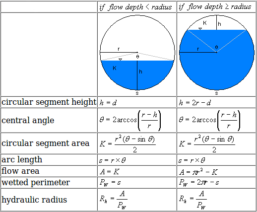
Partially Filled Pipes
Partially filled pipes are a common scenario in hydraulic engineering where the pipe is not completely full of liquid. The wetted perimeter in such cases is the portion of the pipe's inner circumference that is in contact with the liquid. Calculating the wetted perimeter and other related parameters for partially filled pipes involves understanding the geometry of the pipe and the flow within it.
For a circular pipe with diameter \( D \), partially filled to a depth \( y \), the wetted perimeter \( P \) can be determined using the central angle \( \theta \) that the liquid subtends at the center of the pipe. The central angle \( \theta \) in radians is given by:
\[
\theta = 2 \cos^{-1}\left(\frac{D - 2y}{D}\right)
\]
Once \( \theta \) is known, the wetted perimeter \( P \) is calculated as:
\[
P = \frac{\theta}{2\pi} \cdot \pi D = \frac{\theta D}{2}
\]
The cross-sectional area of flow \( A \) for a partially filled pipe is given by the area of the circular segment formed by the liquid:
\[
A = \frac{D^2}{8} (\theta - \sin(\theta))
\]
Using these equations, one can determine the hydraulic radius \( R \), which is important for further hydraulic calculations:
\[
R = \frac{A}{P}
\]
These calculations are crucial for determining the flow characteristics using Manning's equation, which is frequently used for gravity-driven flow in open channels and partially filled pipes:
\[
Q = \frac{1}{n} A R^{2/3} S^{1/2}
\]
Where:
- \( Q \) is the flow rate
- \( n \) is the Manning's roughness coefficient
- \( A \) is the cross-sectional area of flow
- \( R \) is the hydraulic radius
- \( S \) is the slope of the energy gradient
The value of \( n \) depends on the material of the pipe and its surface roughness. Typical values range from 0.009 to 0.015 for smooth surfaces like concrete, and higher for rougher surfaces.
Understanding these principles and applying the formulas allows engineers to accurately predict and manage the flow in partially filled pipes, ensuring efficient design and operation of hydraulic systems.
Applications in Engineering
The concept of wetted perimeter is fundamental in various engineering applications, particularly in the design and analysis of hydraulic systems. Here are some of the key applications:
-
Civil Engineering:
Drainage Systems: Wetted perimeter calculations help in designing efficient drainage systems by determining the flow characteristics in open channels and pipes.
Irrigation Systems: It is crucial for designing irrigation channels to ensure optimal water distribution with minimal losses.
Flood Management: Understanding the wetted perimeter assists in flood modeling and designing flood control measures to manage excess water during heavy rainfall.
-
Environmental Engineering:
Water Resource Management: Wetted perimeter is used to assess and manage water resources, including river restoration projects and water supply systems.
Pollution Control: Designing channels and pipes for wastewater management involves wetted perimeter calculations to optimize flow and reduce contamination.
-
Hydrology:
River and Stream Analysis: Wetted perimeter is essential for analyzing river flow, sediment transport, and erosion processes, contributing to the understanding of river dynamics.
Hydraulic Modeling: It plays a crucial role in hydrological studies, including flood modeling and predicting river behavior under various conditions.
-
Mechanical Engineering:
Pipe Flow Analysis: In pipe systems, wetted perimeter helps in determining friction losses and optimizing the design for efficient fluid transport.
Heat Exchangers: Wetted perimeter calculations are used to design heat exchangers where fluid flow and heat transfer efficiency are critical.
Overall, the wetted perimeter is a critical parameter in various engineering disciplines, aiding in the design, analysis, and optimization of systems involving fluid flow. Its applications span across civil, environmental, hydrological, and mechanical engineering, highlighting its versatility and importance in engineering solutions.
Hydraulic Radius Calculation
The hydraulic radius (\( R_h \)) is a crucial parameter in hydraulic engineering, representing the efficiency of fluid flow within a pipe or channel. It is defined as the ratio of the cross-sectional area of the flow to the wetted perimeter.
The formula for calculating the hydraulic radius is:
\( R_h = \frac{A}{P} \)
- \( R_h \) = Hydraulic radius
- \( A \) = Cross-sectional area of the flow
- \( P \) = Wetted perimeter
Calculation Steps for Circular Pipes
- Determine the diameter (\( D \)) of the pipe.
- Calculate the cross-sectional area (\( A \)) of the pipe using the formula:
\( A = \pi \left( \frac{D}{2} \right)^2 \)
- Calculate the wetted perimeter (\( P \)) of the pipe using the formula:
\( P = \pi D \)
- Compute the hydraulic radius (\( R_h \)) by dividing the cross-sectional area by the wetted perimeter:
\( R_h = \frac{A}{P} = \frac{\pi \left( \frac{D}{2} \right)^2}{\pi D} = \frac{D}{4} \)
Calculation Steps for Non-Circular Channels
- Determine the shape and dimensions of the channel.
- Calculate the cross-sectional area (\( A \)) of the flow. For example, in a rectangular channel with width (\( b \)) and depth (\( h \)):
\( A = b \times h \)
- Calculate the wetted perimeter (\( P \)) of the channel. For a rectangular channel:
\( P = b + 2h \)
- Compute the hydraulic radius (\( R_h \)) by dividing the cross-sectional area by the wetted perimeter:
\( R_h = \frac{A}{P} = \frac{b \times h}{b + 2h} \)
Importance of Hydraulic Radius
The hydraulic radius is essential in understanding and designing fluid flow systems. It affects several key parameters, such as:
- Flow Efficiency: A higher hydraulic radius indicates more efficient flow, reducing energy losses due to friction.
- Flow Velocity: It directly influences the velocity of the fluid within the channel or pipe.
- Flow Resistance: Lower resistance in the channel or pipe can be achieved by optimizing the hydraulic radius.
Applications
Hydraulic radius calculations are widely used in various engineering fields, including:
- Civil Engineering: For the design of irrigation systems, drainage systems, and open channels.
- Hydrology: In flood modeling and river flow analysis.
- Environmental Engineering: For water resource management and river restoration projects.
- Fluid Mechanics: To analyze and design fluid flow in pipes and channels.
Manning's Equation and Flow Rate
Manning's Equation is a widely used empirical formula for calculating the flow rate of water in open channels and gravity-driven pipes. It was introduced by the Irish engineer Robert Manning in 1889. The equation is especially useful because it accounts for the pipe's slope, roughness, and cross-sectional shape, allowing for accurate flow calculations under various conditions.
The Manning's Equation is given by:
\[ Q = \frac{1}{n} A R^{2/3} S^{1/2} \]
where:
- Q is the flow rate (m³/s or ft³/s)
- n is the Manning's roughness coefficient (dimensionless), which depends on the pipe material and surface roughness
- A is the cross-sectional area of flow (m² or ft²)
- R is the hydraulic radius (m or ft), defined as the ratio of the cross-sectional area of flow (A) to the wetted perimeter (P): \( R = \frac{A}{P} \)
- S is the slope of the pipe or energy gradient (dimensionless), typically approximated as the ratio of the vertical drop in elevation (h) to the horizontal pipe length (L): \( S = \frac{h}{L} \)
To use Manning's Equation for gravity pipe flow calculations, follow these steps:
- Determine the pipe's cross-sectional area (A) and wetted perimeter (P) based on the pipe's diameter (D) and flow depth (if the pipe is partially full). For a circular pipe running full, \( A = \frac{\pi D^2}{4} \) and \( P = \pi D \).
- Calculate the hydraulic radius (R) using the formula \( R = \frac{A}{P} \).
- Estimate the slope of the pipe (S) by measuring the vertical drop in elevation (h) and the horizontal pipe length (L), and then calculating the ratio: \( S = \frac{h}{L} \).
- Obtain the Manning's roughness coefficient (n) for the pipe material. Typical values range from 0.009 to 0.015 for concrete pipes and 0.012 to 0.035 for corrugated metal pipes. The exact value depends on the material and surface roughness.
- Plug the values for A, R, S, and n into Manning's Equation and calculate the flow rate (Q).
Keep in mind that Manning's Equation assumes steady, uniform flow and is best suited for relatively simple pipe systems. For more complex systems or non-steady flow conditions, other methods or computational models might be more appropriate.
Factors Affecting Wetted Perimeter
The wetted perimeter of a pipe or channel is influenced by several factors, which in turn affect the hydraulic efficiency and flow characteristics. Understanding these factors is crucial for designing and managing hydraulic systems. Here are the key factors:
- Channel Shape: The geometry of the channel or pipe greatly impacts the wetted perimeter. For instance, a circular pipe will have a different wetted perimeter compared to a rectangular channel for the same cross-sectional area.
- Flow Depth: The depth of flow in a channel or pipe affects the wetted perimeter. In open channels, as the water depth increases, the wetted perimeter also increases.
- Roughness of Channel Surface: The roughness or texture of the channel surface influences the wetted perimeter. Rough surfaces increase friction and hence the wetted perimeter, while smooth surfaces reduce it.
- Flow Regime: Whether the flow is laminar or turbulent can affect the wetted perimeter. Turbulent flows can lead to greater interaction with the channel walls, increasing the wetted perimeter.
- Channel Slope: The slope or gradient of the channel affects the velocity and depth of the flow, which in turn influences the wetted perimeter.
In summary, these factors are interrelated and must be carefully considered during the design and analysis of hydraulic systems to ensure efficient and effective water flow management.
Practical Examples
Understanding the wetted perimeter through practical examples helps in grasping its applications in real-world scenarios. Here are some examples demonstrating the calculation of the wetted perimeter in different situations:
Example 1: Circular Pipe (Full Flow)
Consider a circular pipe with a diameter \( D \) of 1 meter. Since the pipe is flowing full, the wetted perimeter \( P \) is the same as the circumference of the pipe:
\[
P = \pi D = \pi \times 1 \text{ meter} = 3.14 \text{ meters}
\]
Example 2: Circular Pipe (Partially Filled)
For a circular pipe of diameter 1 meter, partially filled to a height \( h \) of 0.5 meters, the wetted perimeter involves calculating the arc length and the width of the water surface. The central angle \( \theta \) can be calculated as:
\[
\theta = 2 \cos^{-1}\left(\frac{D - 2h}{D}\right) = 2 \cos^{-1}\left(\frac{1 - 1}{1}\right) = 2 \cos^{-1}(0) = \pi \text{ radians}
\]
The arc length \( L \) is given by:
\[
L = \frac{\theta}{2\pi} \times \pi D = \frac{\pi}{2\pi} \times \pi \times 1 = \frac{\pi}{2} \text{ meters}
\]
The wetted perimeter \( P \) is:
\[
P = L + 2h = \frac{\pi}{2} + 2 \times 0.5 = 1.57 + 1 = 2.57 \text{ meters}
\]
Example 3: Rectangular Channel
For a rectangular channel with a width \( b \) of 2 meters and a depth \( h \) of 1 meter, the wetted perimeter \( P \) is calculated as:
\[
P = b + 2h = 2 + 2 \times 1 = 4 \text{ meters}
\]
Example 4: Trapezoidal Channel
Consider a trapezoidal channel with a bottom width \( b \) of 3 meters, side slopes \( s \) of 2 (horizontal:vertical), and a depth \( h \) of 1 meter. The wetted perimeter \( P \) is:
\[
P = b + 2\sqrt{h^2 + (sh)^2} = 3 + 2\sqrt{1^2 + (2 \times 1)^2} = 3 + 2\sqrt{1 + 4} = 3 + 2\sqrt{5} \approx 3 + 4.47 = 7.47 \text{ meters}
\]
Example 5: Natural Stream
In a natural stream with irregular banks, assume the wetted perimeter needs to be measured directly. If the left bank measures 3 meters, the streambed 5 meters, and the right bank 4 meters, the total wetted perimeter \( P \) is:
\[
P = 3 + 5 + 4 = 12 \text{ meters}
\]
Example 6: Elliptical Pipe
For an elliptical pipe with a major axis \( a \) of 2 meters and a minor axis \( b \) of 1 meter, fully filled, the wetted perimeter \( P \) can be approximated using Ramanujan's formula:
\[
P \approx \pi \left[ 3(a + b) - \sqrt{(3a + b)(a + 3b)} \right] = \pi \left[ 3(2 + 1) - \sqrt{(3 \times 2 + 1)(2 + 3 \times 1)} \right] = \pi \left[ 9 - \sqrt{7 \times 5} \right] = \pi \left[ 9 - \sqrt{35} \right] \approx \pi \left[ 9 - 5.92 \right] \approx \pi \times 3.08 \approx 9.68 \text{ meters}
\]
Advanced Calculations
Advanced calculations of the wetted perimeter involve detailed understanding and application of fluid dynamics principles. Here, we will explore some complex scenarios and provide step-by-step methodologies for accurate determination of the wetted perimeter in various conditions.
1. Irregular Pipe Shapes
For pipes with irregular shapes, the wetted perimeter can be determined using numerical integration techniques. Consider an irregular cross-section where the boundary can be defined by a function \( f(x) \). The wetted perimeter \( P \) is calculated as:
\[
P = \int_{a}^{b} \sqrt{1 + \left(\frac{df(x)}{dx}\right)^2} \, dx
\]
This integral can be evaluated using numerical methods such as the trapezoidal rule or Simpson's rule.
2. Non-Circular Curved Pipes
For non-circular curved pipes, the wetted perimeter depends on the curvature and the extent of fluid contact. Consider a pipe with an elliptical cross-section:
\[
P = \pi \left[ 3(a + b) - \sqrt{(3a + b)(a + 3b)} \right]
\]
where \( a \) and \( b \) are the semi-major and semi-minor axes of the ellipse, respectively.
3. Partially Filled Circular Pipes
When a circular pipe is partially filled with fluid, the wetted perimeter is a segment of the circle's circumference. If the fluid forms an angle \( \theta \) at the center of the pipe, the wetted perimeter \( P \) is given by:
\[
P = R \theta
\]
where \( R \) is the radius of the pipe and \( \theta \) is in radians. The angle \( \theta \) can be found from the depth of the fluid \( d \) using:
\[
\theta = 2 \cos^{-1} \left(1 - \frac{d}{R}\right)
\]
4. Wetted Perimeter in Open Channel Flow
For open channels with complex shapes, the wetted perimeter is the length of the boundary in contact with the fluid. Consider a trapezoidal channel:
- Base width \( B \)
- Side slopes \( z \) (horizontal distance per unit vertical distance)
- Flow depth \( h \)
The wetted perimeter \( P \) is:
\[
P = B + 2h\sqrt{1+z^2}
\]
5. Combined Flow Sections
In systems with combined flow sections (e.g., circular pipes connecting to rectangular channels), the wetted perimeter is the sum of individual sections:
\[
P_{\text{total}} = P_1 + P_2 + \ldots + P_n
\]
Each section's wetted perimeter can be calculated using the respective formulas and then summed to obtain the total wetted perimeter.
6. Computational Fluid Dynamics (CFD) Approach
For highly irregular geometries and complex flow conditions, using Computational Fluid Dynamics (CFD) software can provide precise wetted perimeter calculations. CFD simulations solve the Navier-Stokes equations to model fluid flow and determine the wetted boundary accurately.
Conclusion
Advanced calculations for the wetted perimeter require understanding of various mathematical and computational methods. These techniques enable precise determination of the wetted perimeter, crucial for designing efficient hydraulic systems.
Design Considerations
When designing pipes and channels for fluid flow, several factors must be considered to ensure efficiency and effectiveness. Here are key design considerations related to the wetted perimeter and hydraulic radius:
- Hydraulic Radius Calculation: The hydraulic radius (Rh) is crucial for determining flow characteristics. It is defined as the cross-sectional area (A) divided by the wetted perimeter (P). The formula is:
R_h = \frac{A}{P} - Channel Shape: The shape of the channel impacts the wetted perimeter and thus the hydraulic radius. Different shapes have different efficiencies:
- Circular pipes (full):
P = 2\pi r - Rectangular channels:
P = b + 2y - Trapezoidal channels:
P = b + 2y\sqrt{1 + z^2}
- Circular pipes (full):
- Material and Surface Roughness: The roughness of the pipe material affects friction losses. Smoother materials reduce the wetted perimeter in contact with the fluid, increasing the hydraulic radius.
- Flow Regime: The hydraulic radius helps determine the flow regime (laminar or turbulent). This is critical for predicting flow behavior and designing for optimal performance.
- Slope and Gradient: The slope of the pipe or channel affects the hydraulic radius and flow velocity. The Manning's equation, which includes the hydraulic radius, is used to calculate flow velocity:
V = \frac{1}{n} R_h^{2/3} S^{1/2} - Environmental and Economic Considerations: Designs should balance efficiency with environmental impact and cost. Choosing the right materials and dimensions can optimize both performance and sustainability.
In summary, careful consideration of these factors ensures that pipes and channels are designed to maximize flow efficiency, minimize friction losses, and meet the required specifications for various engineering applications.
Conclusion and Summary
In conclusion, the wetted perimeter is a critical parameter in the design and analysis of fluid flow in pipes and open channels. It represents the length of the boundary in contact with the fluid, influencing various hydraulic characteristics such as flow rate, velocity, and hydraulic radius.
The calculation of the wetted perimeter varies with the shape of the channel or pipe. For circular pipes, the wetted perimeter depends on the internal circumference and the fill level of the pipe. In rectangular channels, it is the sum of the bottom width and the heights of the sides in contact with the fluid. Each configuration requires specific formulas to accurately determine the wetted perimeter, which is essential for designing efficient fluid transport systems.
Understanding the wetted perimeter is essential for practical applications in civil and hydraulic engineering. Accurate calculations ensure the effective design of water supply systems, drainage networks, and irrigation channels. The wetted perimeter also plays a significant role in determining the hydraulic radius, which is crucial for calculating the flow characteristics using Manning's equation.
Moreover, factors such as the roughness of the channel's surface and the shape of the cross-section significantly impact the wetted perimeter. These factors must be considered to ensure precise hydraulic modeling and efficient system design.
In summary, mastering the concepts of wetted perimeter and its associated calculations enables engineers to create robust designs for various water conveyance systems, ensuring optimal performance and sustainability. Future advancements in computational tools and modeling techniques will further enhance our ability to predict and manage fluid flow in diverse engineering applications.
Độ Sâu Bình Thường Cho Ống Tròn Đầy Một Phần (Phần 1)
READ MORE:
Cách Tìm BÁN KÍNH THỦY LỰC và CHU VI ƯỚT – Hình Chữ Nhật, Hình Thang, Hình Tròn